LTE Authentication
Delving into the underlying crypto behind LTE Authentication — A step by step breakdown
LTE
5G
Cryptography
Networking
By: Sudheesh Singanamalla, Esther Jang on 18 Feb 2020
Acknowledgements: Matthew Johnson, Spencer Sevilla, Kurtis Heimerl
Authentication refers to the idea of validating the identity of a user or a device trying to access the resources provided by a given service and Authorization helps in controlling the access to these resources. In the case of LTE and wireless networks, authentication is used to enable a user device such as a mobile phone or an IoT device to connect to the network and use the resources provided by the network such as calling, Internet/data services or messaging services. Authorization is used to check if the user connected to the network can actually be granted services. For example:
- Authentication: Check if the user device with the SIM card is actually owned by the network to which it is trying to connect to
- Authorization: Check if the user has sufficient credit balance to access the data services at 1 MBps.
So how does this really happen in LTE Networks?
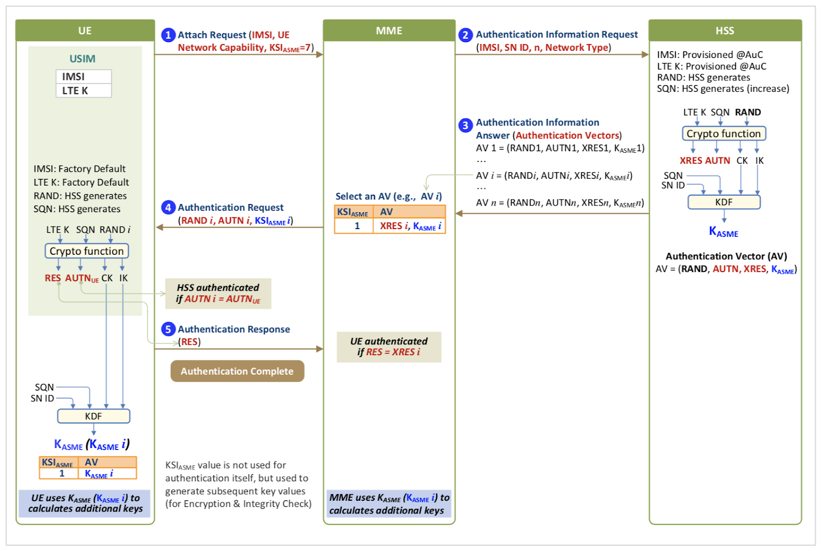
LTE networks use the Evolved Packet System Authentication and Key Agreement (EPS-AKA) procedure for bidirectionally authenticating the user i.e. authenticating the user to the network and the network to the user.

Let’s break this image down into the parts that we really need. Each USIM card produced by the network operator contains a cryptographic key, Ki,which is also known to the network operator and stored in the HSS. To authenticate, this key is used to:
- Have the UE authenticate the network
- Why? This is to prove that the UE is indeed speaking to the network to which it is supposed to be talking to in the first place
- Have the network authenticate the UE
- Why? This is to ensure that the UE who has actually paid for the network service and belongs to the network is the one who receives access to it.
Protocol Call Flow for Authentication
Attach Request
In order to join the network, the UE firstly sends an attach request to the MME via the eNB (base station) with the corresponding PLMN Identity, Mobile Country Code (MCC), Mobile Network Code (MNC) and a cell ID. The MME sends a back a response to the UE requesting for an IMSI. This message is known as an Identity Request and is sent as a Downlink NAS Transport message. The uplink NAS message from the UE is an Identity Response which contains the mobile identity (IMSI) value thereby completing the Attach request phase of the protocol.
Authentication Information Request and Response
After receiving the Identity Response, The MME sends a diameter (S6a) message called Authentication Information Request (AIR) from the MME to the HSS and sends the corresponding mobile identity. The HSS on receiving this information computes is responsible for:
- Checking if the subscriber corresponding to the IMSI value is a genuine subscriber belonging to the network. Performing the necessary cryptographic operations to generate an authentication vector (AV) necessary to challenge the UE for authentication.
- The response from the HSS to the MME i.e. Authentication Information Answer (AIA) contains the authentication information which includes a random byte array denoted by RAND, the expected response from the UE to the MME denoted by XRES, the authentication response denoted by AUTN, and a shared key called the Key Access Security Management Entries denoted by Kasme.
So how are these values generated? Let’s dig deeper into the HSS to see what happens to create this Authentication Information Answer (AIA) response.
Authentication Vector Generation
The HSS contains the LTE key Ki which is the same as the key that’s present on the USIM of the UE. In addition, the SIM card also contains the network operators key OPc and an Authentication Management Field (AMF). These are two very critical secret keys which should be safeguarded by the network operators at any cost.
On receiving the request, the HSS checks for the existence of a database record corresponding to the subscriber and retrieves the Ki, OPc values. For simplicity reasons, let us assume that the network operator knows the last used SQN number, we look into how to obtain this value in a later blog post.
- The HSS then generates a 16 byte random value and stores it in RAND.
- The AMF, Ki, SQN and RAND values are fed into the Milenage algorithm which generates the responses for AUTN, Anonymity Key (AK), Cipher Key (CK), Integrity Key (IK) and an expected response XRES.
- Another set of algorithms use the generated AK, CK, IK from the Milenage algorithm to compute Kasme.
How does Milenage Really work?
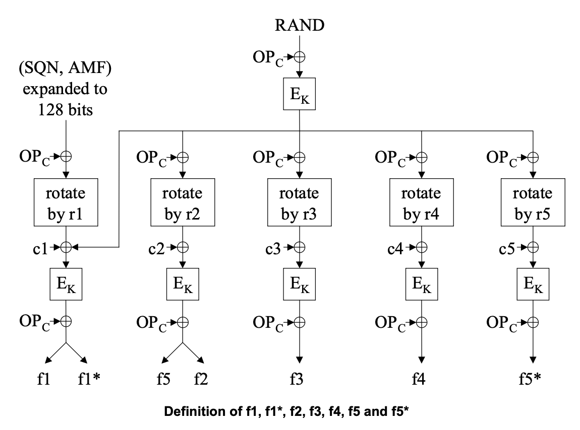
Milenage consists of a series of functions denoted by f1, f2, f3, f4, f5 according to the 3GPP specification. These are also sometimes written in open source cores as f1 and f2345 denoting the execution of each of the functions f2,f3,f4,f5 and collectively returning a response.

The function f1 takes OPc, Ki, RAND, SQN and AMF values and performs:
- For each byte of RAND, OPc performs a XOR operation and stores the result into a temporary value (TMP1).
- Run AES128 bit encryption on TMP1 using Ki
- Expand the byte arrays of SQN, AMF to 128 bits i.e. creating
SQN || AMF || SQN || AMFand storing it in TMP2 - Perform TMP2 xor OPc and rotate it by a constant r1 i.e. 8 bytes (0x40)
- TMP3 = TMP2 ⊕ OPc with r1 byte rotation
- xor the value in TMP3 with TMP1
- AES128 encrypt TMP3 using Key Ki and assign the value to TMP1
- xor the value in TMP1 with OPc as F1_RES
- The first 8 bytes of the F1_RES correspond to MAC_A which is a 64 bit network authentication code.
- The second 8 bytes of the F1_RES correspond to MAC_S which is a 64 bit resynchronization authentication code.
- Return MAC_A, MAC_S as the result of F1.

The function f2345, uses the OPc, Ki, RAND, to generate XRES, CK, IK, AK. The function has constants r2, r3, r4, and r5 corresponding to the constant of bytes to rotate the array. In addition there are constants c2, c3, c4, and c5 which are constants used in different functions. This is done by:
- Computing RAND xor OPC and storing it in TMP1.
- AES128 encrypt TMP1 using Ki and store the result in TMP2.
- Update TMP1 by performing TMP2 xor OPc.
- Additionally xor the last byte i.e. 15 index, with a constant c1 and rotate by r2=0
- TMP1 = TMP2 ⊕ OPc
- TMP1[15] = TMP1[15] ⊕ 1 where c1 is a constant with value 1
- AES128 encrypt TMP1 using key Ki and store the result in TMP3
- Perform TMP3 = TMP3 ⊕ OPc
- The result of f5 is the first 6 bytes of TMP3 i.e. TMP3 bytes 0 - 5 which is AK
- The result of f2 is the last 8 bytes of TMP3 i.e. TMP3 bytes 8 - 15 which is XRES
- Perform TMP2 xor OPc and assign the result to TMP1 with r3 = 4 bytes
- TMP1 = TMP2 ⊕ OPc with r3 byte rotation
- xor the last byte of TMP1 with a constant c3 = 2
- AES128 encrypt TMP1 using key Ki and copy the result into CK
- For f3, Perform xor of CK with OPc and assign the result to final value of CK
- Similar to step 6, perform the TMP2 xor OPc and assign the result to TMP1 with r4=8 bytes and xor with a constant c4=4.
- TMP1 = TMP2 ⊕ OPc with r4 byte rotation
- xor the last byte of TMP1 with constant c4=4
- AES128 encrypt TMP1 using key Ki and copy the result into IK
- For f4, Perform xor of IK with OPc and assign the result to final value of IK
After computing the MAC_A, MAC_S, AK, IK, CK, and XRES. The AUTN value is obtained by concatenating the SQN xor AK, with AMF and MAC_A value.
AUTN = (SQN AK) || AMF || MAC_A
Note: The MAC_S value is used in case of synchronization failures of SQN. We will cover this in a later blog post.
The results of milenage and other information i.e. AUTN, SQN, XRES, CK, IK, AK along with PLMN are used to compute the Kasme value by doing:
- k =
CK || IK - Initialize a 14 byte buffer s
- Assign the first byte of s as 0x10
- Copy the 3 bytes of PLMN into s
- Assign 5th and 6th byte as 0x00 and 0x03
- Assign the next 6 bytes as SQN AK
- Assign the last two bytes as 0x00 and 0x06
- Perform an HMAC-SHA256 using Key k from step 1 and s as the message.
- The corresponding output from this function is the Kasme
The Authentication Information Answer contains the AUTN, RAND, Kasme, XRES which is sent by the HSS to the MME as a diameter response.
Authentication Request and Response
The MME removes the XRES from the AIA request and packages the the (AUTN, RAND, Kasme) into an authentication vector and sends an Authentication Request to the UE. The UE knows the SQN value to use and contains the corresponding Ki, OPc values in the USIM and executes the Milenage algorithm using the RAND value that has been provided.
The UE computes a new AUTN value and compares it to the value that has been provided in an effort to authenticate the network to the UE. Once the UE successfully validates the network it is communicating with, it generates a RES which is sent as an Authentication Response to the MME. The MME validates if the response provided RES matches the expected response XRES and sends a successful/unsuccessful authentication message to the UE. The UE is now authenticated and attached to the network.
The UE further computes the Kasme values to compute the necessary AK, CK, IK keys used for encryption and integrity checks in further communications.